TIP121 Transistor Pinout, Equivalent, Uses, Specs
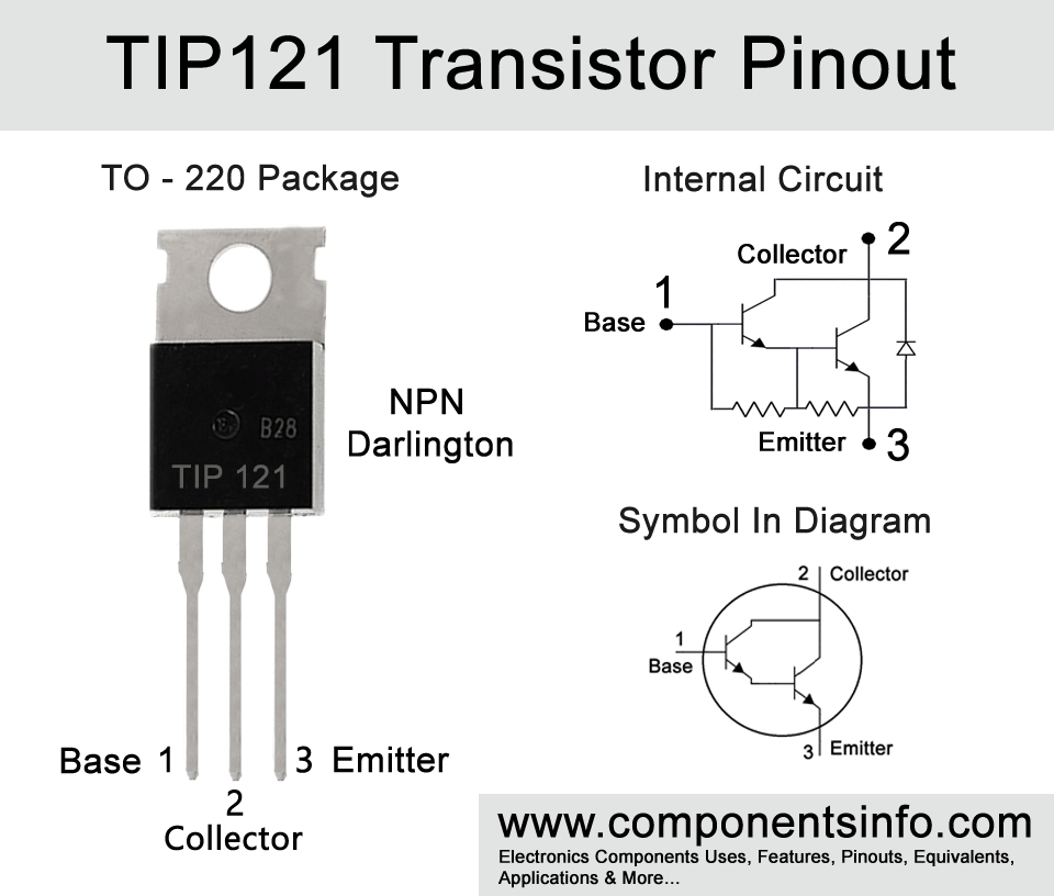
Today we are going to discuss about TIP121 Transistor Pinout, Equivalent, Uses, Specs, datasheet, how and where to use it and other useful information about this NPN darlington pair transistor.
Features / technical specifications:
- Package Type: TO-220
- Transistor Type: NPN
- Max Collector Current(IC): 5A
- Max Collector-Emitter Voltage (VCE): 80V
- Max Collector-Base Voltage (VCB): 80V
- Max Emitter-Base Voltage (VEBO): 5V
- Max Collector Dissipation (Pc): 65 Watt
- Minimum & Maximum DC Current Gain (hFE): 1000
- Max Storage & Operating temperature: -65 to +150 Centigrade
PNP Complementary:
PNP Complementary of TIP121 is TIP126
Replacement and Equivalent:
2N6530, 2N6532, 2N6388, 2N6043, TIP122, 2SD633, 2SD634, 2SD1195, 2N6044, 2N6045, 2N6045G, 2SD1892, TIP101, TIP131, BDT63B, BDW43, TIP142T, MJF122, MJF6388 (These are the nearest possible substitute or alternate transistors that can be used in the place of TIP121. But pin configuration of these transistors may different from TIP121, therefore check pin configurations before replacing in your circuit.)
TIP122 Transistor Explained / Description:
A darlington transistor is a pair of two BJT transistors in one transistor package connected such a way to provide very high gain at output. It is a simple technique to amplify a low level or low gain signals to very high level or high gain with no special circuitry. The input signal is first amplified by the first transistor and then further amplified by the other. The darlington pair can also be made by using two separate BJT transistors and it is also readily available by manufacturers. TIP121 is also a readymade darlington pair transistor that contains two transistors inside its single TO-220 package. The transistor is having very interesting specs / features which makes it an ideal transistor to use in your circuits. It can drive max collector load of 5A or 5000mA with only requirement of 120mA at its base. The max load driving voltage is 80V means you can drive the load through this transistor from few volts to 80V. The max collector dissipation of 65 Watts with gain of 1000 also makes it ideal to use for signal amplifications.
Where We Can Use it & How to Use:
TIP121 can be used for both switching and amplification purposes. As a switch it is able to drive load of 5A which is a quite good collector current to drive variety of loads at a time in electronic circuits for example motors, relays, part of a circuit, high power LEDs etc. It can also be used at the output of arduino, raspberry Pi and other platforms to drive multiple loads. Additionally it can be used at the output of almost any microcontroller. Moreover it can also be used as an amplifier to amplify low level or low gain audio signals and other types low level or low gain signals to very high level or high gain with its high gain capabilities.
Applications:
Motor Drivers
Battery Chargers
Audio Amplifier Stages
Audio Power Amplifier Circuits
Audio Preamplifiers and Its Stages
Driving or Switching Loads under 5A
Output of Microcontrollers
How to Safely Long Run in a Circuit:
It is always suggested to not touch the maximum ratings of an electronic component to receive long term and stable performance from a component. If you want to use TIP121 in your circuit it is recommended to always keep these points in your mind:
- Do not drive load more than 80V and 5A.
- Always use a suitable heatink with the transistor.
- Always use a suitable base resistor to provide desired base current to the transistor.
- Do not store or use this transistor in temperature below -65 centigrade and above +150 centigrade.
Note: As suggested above 80V and 5A are the maximum ratings of this transistor, using components on their maximum ratings provide stress on the components or may shorten their life span in a circuit. If the maximum collector-emitter voltage is 80V you can stay under 60V and if the maximum collector current is 5A then you can stay under 4A with a suitable heatsink.
Datasheet:
To Download the datasheet just copy and paste the below link in your browser.
https://pdf1.alldatasheet.com/datasheet-pdf/view/25367/STMICROELECTRONICS/TIP121.html


