TIP117 Transistor Pinout, Applications, Features, Where and How to Use It
TIP117 is a medium power transistor designed for general purpose applications of switching and amplification purposes. This post explains TIP117 transistor pinout, applications, features, where and how to use it and other important information about this transistor.
Absolute Maximum Ratings:
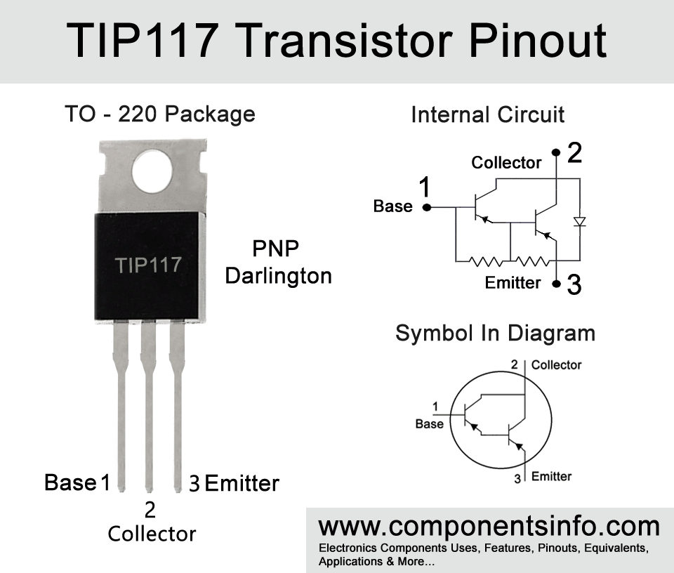
- Package Type: TO-220
- Transistor Type: PNP Darlington
- Max Collector Current(IC): -2A
- Max Collector-Emitter Voltage (VCE): -100V
- Max Collector-Base Voltage (VCB): -100V
- Max Emitter-Base Voltage (VEBO): -5V
- Max Collector Dissipation (Pc): 50 Watt
- Minimum & Maximum DC Current Gain (hFE): 500 To 1000
- Max Storage & Operating temperature: -65 to +150 Centigrade
PNP Complementary:
PNP Complementary of TIP117 is TIP112
Replacement and Equivalent:
TIP107, TIP127, TIP137, 2SB886, 2SB884, 2SB885, 2SB1481, 2SB1252, 2SB1227, NTE262, MJE6024, BD902, BD652, BD6050, 2SB712.
2SD669 Transistor Explained / Description:
TIP117 is a PNP darlington transistor designed to be used in switching (low speed type) and amplification applications. The transistor has many good features which are low collector-emitter saturation voltage means it has low voltage drop between collector and emitter when the transistor is working in fully ON condition. This feature ensures low power waste and makes the transistor energy efficient. Another feature of the transistor is a high DC current gain of 1000 this indicates how efficiently the transistor can amplify the input signal or current, made for industrial use means it is specially built to last longer, it is robust and reliable to use in machinery. The another feature is the high collector to emitter voltage of up to -100V makes it useful for applications that require to drive of high voltage loads such as power supplies, motors, relays, high voltage amps, test equipment, laser systems, etc.
The absolute maximum ratings of the transistors are collector to base voltage of -100V, emitter to base voltage is -5V, collector current is -2A, pulsed collector current is -4A, base current is -50mA, and collector dissipation 50W.
All the above features and characteristics make this transistor a robust device to use in a wide variety of commercial and industrial applications.
Where We Can Use it & How to Use:
This transistor can be used in a wide variety of general purpose applications. It can be used in power supplies, driving circuits, amplification circuits, switching circuits, etc. To use the transistor it is important to know the absolute maximum ratings of the transistor and do not use it on its max ratings. Moreover, it is also suggested to stay at least 20% below from its absolute maximum ratings. Here is the easy guide to use this transistor in your design or circuits, first of all, understand your application’s requirements means what are the voltage and current levels you require to control if it is a switching circuit or amplify it if is an amplifier circuit.
Then determine the pinout of the transistor and connect the collector to the negative of the load and the positive side of the load will be connected to the positive supply of the circuit. The emitter will be connected to the negative supply of the circuit and the base of the transistor will be connected with the input signal. It is also crucial to supply the required base current, the details about this can be in the datasheet as (IB) recommended base current for different requirements from which you can understand the suitable resistor value to provide only the required current to the transistor base for a specific load or condition.
Applications:
Switching
Battery Chargers
Power Supplies
Audio Amplifier
Motor Drivers
Solar Applications
Battery Operated Applications
How to Safely Long Run in a Circuit:
For safe operation and good performance, it is important to understand the safe operating guidelines of the transistor. First of all it is important to not use the transistor to its absolute maximum ratings and always stay below these values we recommend at least 20% below. So according to this rule the drive load of the transistor should be under 1.6A and the load voltage should be under 80V. A proper heatsink should be used with the transistor and the temperature around the transistor should be between -65°C to 150°C.
.
Datasheet:
To download the datasheet just copy and paste the below link in your browser.
https://z3d9b7u8.stackpathcdn.com/pdf-down/T/I/P/TIP117_FairchildSemiconductor.pdf