K2611 MOSFET Pinout, Equivalent, Features, Applications, Where and How to Use and More
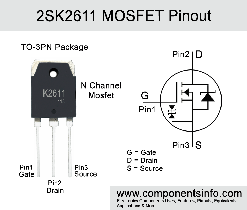
Today we are going to discuss about K2611 MOSFET pinout, equivalent, features, applications, where and how to use and other useful information.
Features / Technical Specifications:
- Package Type: TO-3PN
- Transistor Type: N Channel MOSFET
- Max Continues Drain Current is : 9A
- Max Drain to Source Voltage: 900V
- Single Pulsed Drain Current: 27A
- Max Power Dissipation is: 150W
- Max Gate to Source Voltage Should Be: ±30V
- Max Storage & Operating temperature Should Be: -55 to +175 Centigrade
Replacement and Equivalent:
2SK3843, 2SK4003, 2SK4106, 2SK3766, 2SK3799, 2SK4023, 2SK4014, 2SK3798
2SK2611 Transistors Explained / Description:
If you are looking for a high voltage MOSFET for using in your switching and driving applications then K2611 full part number 2SK2611 might be a good choice. It is an N Channel transistor available in TO-3PN transistor package. Looking at the absolute maximum ratings of the transistor are drian-source voltage is 900V, drain-gate voltage is also 900V, gate-source voltage is ±30V, the max continuous drain current is 9A, max single pulsed drain current is 27A and max power dissipation is 150W.
The transistor has many good features which are
RDS(on) resistance of 1.2 Ohms
The RDS(on) is the resistance between the transistors that occurs when the transistor is in a fully ON state. The transistor has low resistance of only 1.2Ohms.
Upto 9A of current driving capability
The continuous drain current of 9A is an ideal ampere to drive a lot of loads such as relays, LEDs, motors, etc.
Drain-source voltage of 900V
The MOSFET have quite high drain-source voltage due to which it can be used in a variety of high-voltage applications or circuits.
Very small leakage current
2SK2611 is designed specially to have very low leakage current which enhances its overall performance.
Fast switching
The fast switching feature makes this transistor an essential component to use in circuits in which fast switching speed is required. For example LED driver circuits, motor drivers, UPS etc.
Enhancement−mode
Enhancement mode means that it is a type of MOSFET that is closed when no voltage is applied on its Gate. Their opposite are depletion mode MOSFETs which stays open always and when we have to close it we have to apply voltage on its Gate. These features makes this transistor a robust device and also make them to learn something.
Where We Can Use it & How to Use:
As mentioned before this is a versatile device and can be used in wide variety of applications which are low voltage power supplies, control circuits, driver circuits etc. the details list of its applications can be found under the “Applications” below.
How to Use:
Before using the MOSFET in your circuit or if you are going to use it in any it is important to check and confirm its pin configuration. Now the gate pin of the transistor should be connected to the signal source or signal input, source pin should be connected to the ground and drain pin should be connected to the load.
Applications:
Industrial Automation
Lighting Control / controlling and dimming lights intensity
Power Amplification
Voltage Regulation
PWM Applications
Switch mode power supplies (SMPS) and other kinds of power supplies
Solar Power Systems
Control circuits
Switching Circuits
Uninterruptible Power Supplies (UPS)
Motor drives
Inverters
Automotive Electronics
DC-DC Converters
Power Management
Safe Operating Guidelines
For long term performance in your circuit it is essential to consider these safety guidelines:
- Do not use the MOSFET or any other transistor to its maximum ratings and always stay at least 20% below from these values.
- The max drain to source voltage of the transistor is 900V, therefore do not drive load of more than 720V.
- The max continuous drain current s 9A, therefore do not drive load of more than 7.2A.
- Must use a suitable heatsink with the transistor.
- Always store or operate the MOSFET at temperatures above -55°C and below 150 °C.
Datasheet:
To Download the datasheet just copy and paste the below link into your browser.
https://z3d9b7u8.stackpathcdn.com/pdf-down/2/S/K/2SK2611_ToshibaSemiconductor.pdf


