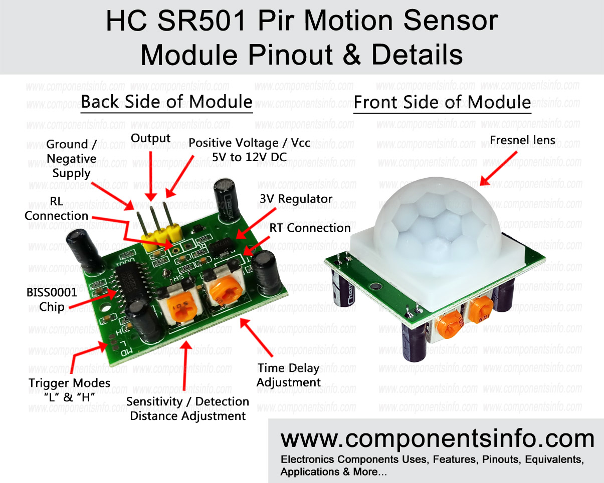
HC SR501 PIR Motion Sensor Module Pinout, Datasheet & Details
HC SR501 is a widely used PIR motion sensor module, in this post you will find the pinout, components, working details of this module. Moreover you will also get to know its applications and how to use this device.
HC SR501 Module Features & Technical Details
- Wide operating voltage range from 4.8V to 20V
- Low power consumption in idle mode only 50uA and 65mA in fully active mode.
- High reliability
- Adjustable sensitivity or detection distance
- Adjustable output time delay (Adjust how much time the output will remain high after the sensor detects a signal)
- Can be used separately without any additional microcontroller or platform like Arduino or Raspberry Pi etc. But you can use them to enhance your project.
- Light sensing control feature (Optional)
- Temperature sensing control feature (Optional)
- Low cost
- Using BISS0001 high quality PIR processing chip
- 120 degree detection angle
- 3 to 7 meters or more detection range
- Easy to communicate with any platform like Arduino or Raspberry Pi etc. and also with all microcontrollers.
- Easy to communicate with analog circuits
HC SR501 PIR Motion Sensor Module Explained / Description
HC SR501 PIR motion sensor also called Pyroelectric, Passive infrared or IR motion sensor. As shown in above image these are small approximately 1.2 x 0.9 inch sized printed circuit board with the PIR motion sensor mounted on the front side and covered by a white fresnel lens that increases the performance of the lens and at the same time protect it. The backside of the PCB is the circuitry with chip and all the components require for processing the information received from the sensor.
Module sensitivity & time delay adjustments
The back side circuitry also contains two variable resistors / adjusters, one variable resistor is given to adjust the sensitivity of the module or in other words we can say the detection range of the module and other one is used to adjust how much time the output will remain high after the PIR module has detected an activity.
Trigger Modes (Optional Modes)
There are two trigger modes in the module marked with the letter “L” and “H” that is also shown in the image above. These are optional modes and there is no need to work on these modes to use the module. By default the module is set on its most common trigger mode. But in case you want to use them then the points are given. To select any mode just connect it with the middle point, you can also use a jumper by soldering three pins on these points. But first it is important to understand what each mode does.
- Trigger Mode “L”
Trigger mode “L” is called single trigger mode. By selecting trigger mode “L” the output will goes high only one time until the time delay period is completed. No matter how many time an object is moved in front of the sensor’s detection range.
- Trigger Mode “H”
Trigger mode “H” is called repeat trigger mode. By selecting trigger mode “H” the output will goes high as many times as the object moves in the detection range of the sensor hence, the time delay started again each time a single motion is detected.
Temperature & light sensing (Optional Modes)
To further enhance the module performance you can also use the temperature sensing and light sensing functions / features of the module. For doing so you don’t have to do any complex thing only you have to add a sensor for each that’s it and after that all the measurement work is done by the BSS0001 chip. By closely looking at the PCB back side you will find 2 holes marked RT and 2 holes marked as RL.
RT
The 2 holes / points marked RT is given to solder a thermistor. A thermistor is a temperature sensing resistor whose resistance changes when the temperature around it changes. Using a thermistor increases the module performance when the temperature goes above +32 Celsius. The thermistor should be mounted from front side of the PCB.
RL
Using the RL feature makes the module to only work in dark which saves battery life a lot by only activating the module in dark / night. For using this feature you only have to solder a LDR or light dependent resistor. An LDR is a light sensing resistor whose resistance changes when the amount of light changes on its surface. The LDR should be mounted from front side of the module.
Working of the Module
The PIR motion sensor module or PIR motion sensing technology works by sensing the change occurs in the infrared radiation or heat generated by a human or animal body in movement or motion. When the pyroelectric sensor detects this phenomenon, it sends an output signal that is further processed by the BISS0001 chip. BISS001 is a low power, high quality and reliable PIR signal processing chip which is built with CMOS technology. After the signal is processed by the chip and if the signal is true then the output of the chip goes high for a certain amount of time that can be adjusted with the variable resistor used in this module.
Applications
Home Security
Office / Work Place Security
Saving Power (Switch ON appliances only when someone is present)
Human Detection
Animal Detection
Industrial Equipment Automation
How to Use
Using HC SR501 PIR Motion Sensor Module Independently
Good news about the HC SR501 module is that it is a complete ready to use module and don’t require any additional components or platforms to add such as Arduino board, Raspberry Pi board etc. You can use it stand alone for your PIR motion sensing purposes. For using this module independently just apply power to the module and connect your device with the output pin and ground pin. One thing should be noted that this PIR motion detector module is a low current device so you cannot control high current devices directly with this module. For driving a high current module you have to use a transistor at the output of the PIR module and then you will be able drive that high current device.
Using HC SR501 Module With Arduino , Raspberry Pi Or Other Boards and Microcontrollers.
You can use Arduino, Raspberry Pi and other platforms to further enhance and versatile your PIR motion sensor projects. Moreover you can connect any microcontroller chip with this module easily. You can find many online tutorials on that, one of the tutorial link is mentioned below.
https://www.instructables.com/id/How-to-Use-PIR-Motion-SensorHC-SR501with-an-Arduin/
Datasheet
To Download the datasheet copy and paste the below link in your browser:
https://cdn-learn.adafruit.com/downloads/pdf/pir-passive-infrared-proximity-motion-sensor.pdf