D1555 Transistor Pinout, Equivalent, Applications, Features and Other Useful Info
D1555 is a power NPN transistor available in TO-30(H)IS package. This article covers D1555 transistor pinout, equivalent, applications, features and other useful info about this device.
Features / Technical Specifications
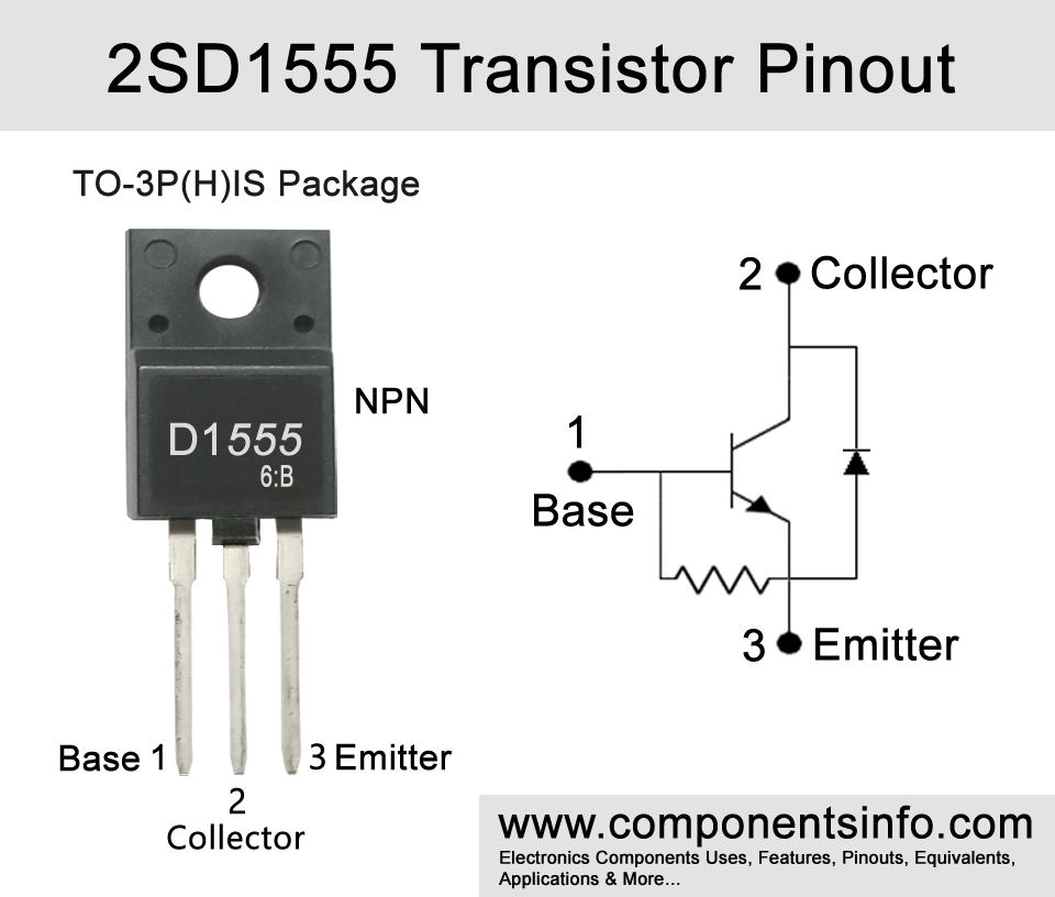
- Package Type: TO-3P(H)IS
- Transistor Type: NPN
- Max Collector Current (IC): 5A
- Max Collector-Emitter Voltage (VCEO): 600V
- Max Collector-Base Voltage (VCBO): 1500V
- Max Emitter-Base Voltage (VEBO): 5V
- Collector Power Dissipation (PC): 50W
- Base Current Continuous (IB): 5A
- DC Current Gain (hFE): 8
- Collector Output Capacitance(COB): 165pF
- Max Storage & Operating temperature range: -55 to +150 Centigrade
Replacement and Equivalent
BUH417, KSC5086, 2SD1556, 2SD1548, 2SD2125
D1555 Transistor Explained / Description
D1555 full part number 2SD1555 is an power NPN transistor available in TO-30(H)IS package. The TO-30(H)IS looks almost the same TO-220F package but it is a slightly bigger TO-220F package. Looking at the pin configuration of the transistor the first pin of the transistor is “Base” second pin is “Collector” and the third pin is “Emitter”.
Above we have discussed the physical characteristics of the transistors, now let’s dive into the transistor’s internal details such as its technical information, features etc.
The transistor is basically designed for color TV horizontal output application which is an important function of a color TV. This application is responsible for displaying images on the screen accurately as received in the signal through the horizontal electron beam. However, the transistor is not only limited to this one application and can also be used for variety of other purposes which we will discuss later in the article.
Looking at the absolute maximum ratings of the transistor, the maximum collector-emitter voltage is 600V, collector-base voltage is 1500V, emitter-base voltage is 5V, collector current is 5A, base current is 2.5A and collector power dissipation is 50W.
The transistor also has many good features such as built-in damper diode which ensures the safety of the transistor by preventing it from the voltage spikes which take place when it turns off. Another feature is low collector saturation voltage, this ensures low voltage drop when the transistor is in fully on state. Low collector saturation voltage has several benefits it increases the overall efficiency of the transistor by less heat generation, good signal amplification, rapid switching, low voltage loss. Additionally, the transistor also has high voltage feature which makes it ideal to use in variety of applications which require a high voltage power transistor.
Where We Can Use it & How to Use
D1555 is designed to use in color TV horizontal output applications but it can also be used for other purposes such as switching applications, Control applications, Audio amplifiers, Voltage regulation, high voltage protection circuits, voltage regulation, power supply and chargers etc.
How to Use:
- To use the transistor first identify its collector, base and emitter pins.
- Connect a base resistor pins to transistor’s base and signal source.
- Connect the emitter pin with the ground and the load will be connected between the collector and the positive supply rail. The load can be a speaker or any type of component you want to power or controlled.
- After that apply power to the transistor or to the circuit from which the transistor’s pins are connected. The input signal must be provided to the base (through the resistor). Without the input signal the transistor will remain off.
- At last test the circuit and make adjustments in the base resistor and biasing components to achieve desired results. A variable resistor can also be used between the transistor and the base resistor to check the performance of the transistor by changing the variable resistor value. But a fixed resistor should always be used with the variable resistor or else there is a change of transistor damaged when the variable resistor value is set to zero.
Applications
DC to DC converters
Audio amplifier circuits
Audio Power Amps
Controlling motors such as Brushed DC and Stepper
Voltage stabilizers
DC to AC converter circuits
Uninterruptable power supplies
Power supply circuits
Battery management circuits
Battery charger circuits
Solar charger circuits
And variety of other applications
Safe Operating Guidelines
To get better performance with the transistor follow these safe operating guidelines to ensure long term and stable performance of the transistor.
- Always operate the transistor under its maximum current and voltage limits and stay at least 20% below from all the ratings written in its datasheet under Absolute Maximum Ratings. Do not use the transistor to its max limits and always stay 20% below from its absolute maximum ratings.
- Always use a proper heatsink
- Maintain the temperature between -55°C to +150°C.
- As mentioned above a suitable base resistor is necessary without a base resistor the transistor could be damaged.
Datasheet
To Download the datasheet just copy and paste the below link in your browser.
https://z3d9b7u8.stackpathcdn.com/pdf-down/2/S/D/2SD1555_SaventIC.pdf