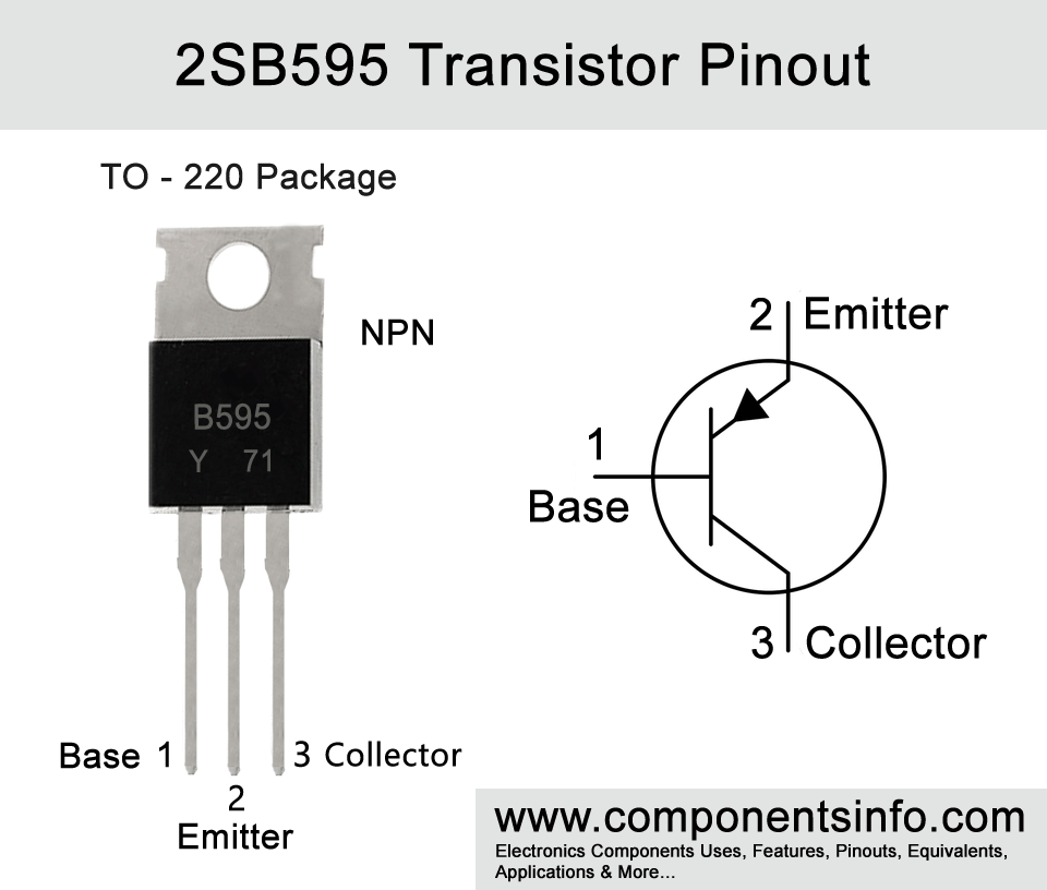
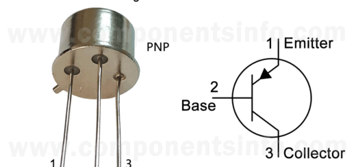
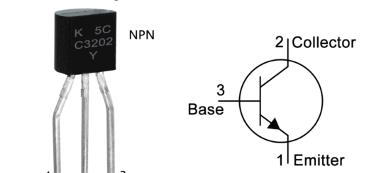
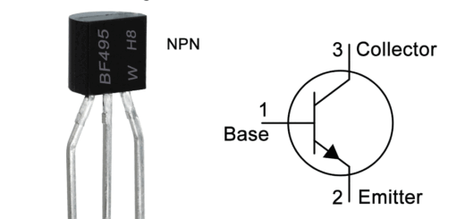
B595 Transistor Pinout, Specifications, Applications, Equivalent, Features and Other Details
2SB595 is a PNP BJT transistor designed for audio amplification purposes. In this article, we are going to discuss B595 transistor pinout, specifications, applications, equivalent, features, and other useful information.
Features / Technical Specifications:
- Package Type: TO-220
- Transistor Type: PNP
- Max Collector Current(IC): -5A
- Max Collector-Emitter Voltage (VCE): -100V
- Max Collector-Base Voltage (VCB): -100V
- Max Emitter-Base Voltage (VEBO): -5V
- Max Collector Dissipation (Pc): 40 Watt
- Max Transition Frequency (fT): 5 MHz
- Minimum & Maximum DC Current Gain (hFE): 40 to 240
- Max Storage & Operating temperature Should Be: -55 to +150 Centigrade
NPN Complimentary:
2SB595 NPN complementary transistor is 2SD525
Replacement and Equivalent:
BD712, BD602, BD712, BD802, 2N6475
2SB595 Transistors Explained / Description:
2SB595 or B595 is a bipolar junction transistor (BJT) designed to use in high power audio amplification applications. It is a PNP transistor available in TO-220 transistor package. It is mostly used in a pair with its NPN complimentary 2SD525 to build high power amplifiers. But it is not limited to use in amplification applications and can also be used for other purposes for example as switching etc.
Looking at the specs of the transistor the maximum collector current of the transistor is -5A, max collector to emitter voltage is -100V, max collector to base voltage is also -100V, maximum emitter to base voltage is -5V, transition frequency is 5MHz, the minimum to maximum DC current gain is 40 to 240 and max collector dissipation is 40W.
The transistor is manufactured in three different types of DC current gain (hFE) classifications that can be determined with the help of the alphabet written after part number. If the alphabet is “R” then the hFE will be 40 to 80, if the alphabet is “O” then the hFE will be 70 o 140 and if the alphabet is “Y” then the hFE will be 120 to 240.
Where We Can Use it & How to Use:
As mentioned above this transistor is designed to be used in high power audio amplification circuits but it is not limited to these uses and can also be used for variety of other purposes for example in power supply circuits, battery charging circuits, audio oscillators to provide different frequency signals, LED drivers etc. The detailed list of its applications can be found below.
Applications:
Audio Amplifiers such as guitar and other audio amplifiers
Power Supplies
Battery Charger Circuits
VCO Circuits
Lighting Circuits
High voltage projects and circuits
Switching Loads under -5A
Safe Operating Guidelines / Absolute Maximum Ratings:
To get better and long term good performance follow the guidelines below.
- It is also recommended by the manufacturer that do not use the transistor on its absolute maximum rating and always stay 20% below from these ratings.
- The maximum collector current of the transistor is -5A therefore do not drive load of more than -4A.
- The max collector to emitter voltage is -100V therefore do not drive load of more than -80V.
- Always use a suitable heatsink with the transistor.
- And always store or operate it at temperature above -55°C and below +150°C.
Datasheet:
To Download the datasheet just copy and paste the below link in your browser.
https://z3d9b7u8.stackpathcdn.com/pdf-down/2/S/B/2SB595-INCHANGE.pdf


