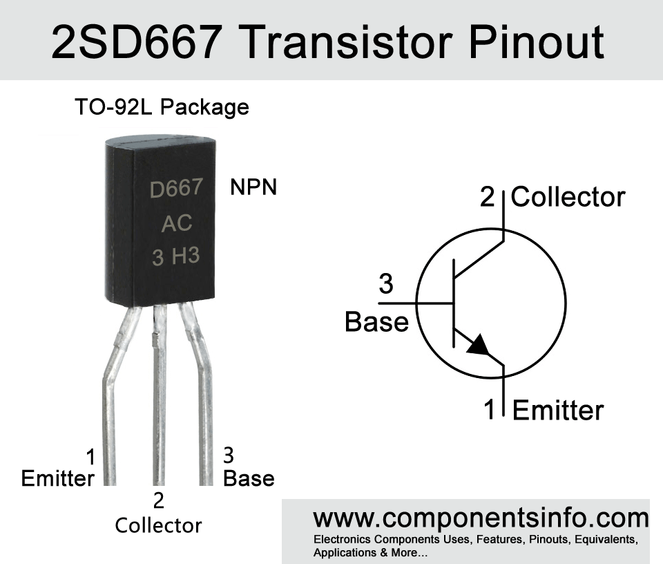
2SD667 Transistor Pinout, Equivalent, Features, Applications, Explanation and More
667, D667 or full name 2SD667 is an NPN BJT transistor available in TO-92L package. This post contains information about 2SD667 transistor pinout, equivalent, features, applications, explanation and other important details about this transistor.
Features / Technical Specifications:
- Package Type: TO-92L / TO-92MOD
- Transistor Type: NPN
- Max Collector Current(IC): 1A
- Max Collector-Emitter Voltage (VCE): 80V
- Max Collector-Base Voltage (VCB): 120V
- Max Emitter-Base Voltage (VEBO): 6V
- Max Collector Dissipation (Pc): 0.9 Watt
- Max Transition Frequency (fT): 140 MHz
- Minimum & Maximum DC Current Gain (hFE): 60– 320
- Max Storage & Operating temperature Should Be: -55 to +150 Centigrade
PNP Complementary
PNP complimentary of 2SD667 is 2SB647
Replacement and Equivalent
2SD974, 2SD667A/B/C, 2SD2213, 2SD2182, 2SD2067, 2SD1930, 2SD1863, 2SD1857, 2SC5060, 2SC4614, 2SC4489, 2SC4145, 2SC3328.
2SD667 Transistor Explained / Description
2SD667 or D667 also searched as 667 is an NPN transistor available in TO-92L package. The transistor is designed to use in low frequency power amplifier applications but due to its good electrical characteristics it can also be used in variety of other applications.
The transistor possesses some of very good features such as collector to emitter voltage of upto 80V which makes it ideal to use in circuits that required high voltages. Moreover, the max collector current is 1A which is also enough to drive a lot of different things in the circuits such as relays, LEDs, power transistors etc. The transition frequency of the transistor is upto 140MHz which is also enhance audio amplification and due to this frequency range this transistor can also be use in RF circuits.
Looking at the maximum ratings of the transistor the collector to base voltage is 120V, collector to emitter voltage (as also discussed above) is upto 80V, emitter to base voltage is 5V, continuous collector current is 1A, and pulsed collector current is 2A and collector power dissipation is 0.9W.
2SD667 is available in three different types according to its DC current gain which can be determined with the alphabet written after the part number. If that alphabet is “B” its hFE will be 60 to 120, if “C” then 100 to 200 and if “D” then its hFE will be 160 to 320.
Where We Can Use it & How to Use
The transistor can be used for L.F power amplification purposes such as in different types of audio amplifier circuits. It can also be used for the amplification of different types of signals. Moreover it can also be used in different type of switching circuits.
The using procedure of the transistor is same as we use other BJT transistor. First of all understand the pinout of the transistor then connect the emitter to the negative supply and collector will be connected to the positive supply through the load. The load can be anything which you want to drive with the transistor, it can be an LED, another transistor, IC, relay etc. The base of the transistor will be connected to the signal from which you want to drive the transistor. A suitable resistor should be used between the signal and base of the transistor to limit the current going in to the base of the transistor. Always drive the load that required under 1A current because the transistor max collector current limit is 1A.
Applications
Audio Amplifiers
Sensor Applications
Motor Drivers
Radio, Tx and RF Amplification
Oscillator
Switching loads under 1000mA
Safe Operating Guidelines / Absolute Maximum Ratings:
To safely operating the transistor it is recommended to not drive the transistor to its absolute maximum ratings and always stay 20% below from the ratings. The max collector current is 1A so according to the 20% rule you should not drive load of more than 800mA, the max collector to emitter voltage is 80V so the load required voltage should be under 64V. The storage and operating temperature limits should also be between -55 °C to +150 °C.
Datasheet
To Download the datasheet just copy and paste the below link in your browser.
https://z3d9b7u8.stackpathcdn.com/pdf-down/2/S/D/2SD667_JiangsuChangjiangElectronics.pdf