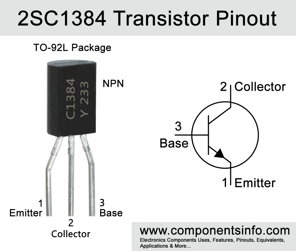
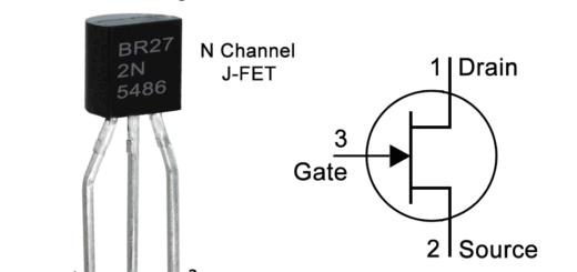
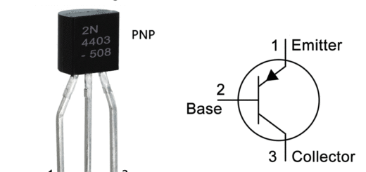
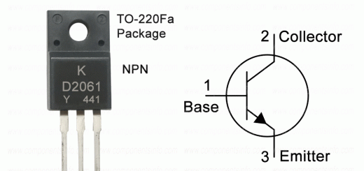
2SC1384 Transistor Pinout, Features, Equivalent, Explanation, Specs and Other Details
2SC1384 or C1384 is an NPN transistor available in TO-92L package. The post describes 2SC1384 transistor pinout, features, equivalent, explanation, specs, and other details.
Features / Technical Specifications:
- Package Type: TO-92L Or TO-92MOD & TO-92
- Transistor Type: NPN
- Max Collector Current(IC): 1A
- Max Collector-Emitter Voltage (VCE): 50V
- Max Collector-Base Voltage (VCB): 60V
- Max Emitter-Base Voltage (VEBO): 5V
- Max Collector Dissipation (Pc): 1 Watt
- Max Transition Frequency (fT): 200 MHz
- Minimum & Maximum DC Current Gain (hFE): 85 – 340
- Max Storage & Operating temperature Should Be: -55 to +150 Centigrade
Replacement and Equivalent
2SC3328, BT3700, ZTX651, ZTX849
PNP Complementary
The PNP complimentary of 2SC1384 is 2SA683
2SB647 Transistor Explained / Description:
2SC1384 is a silicon epitaxial planer type bipolar junction NPN transistor manufactured in TO-92L Or TO-92MOD package but some manufacturers also make it in TO-92 package. It is designed to use in LF power amplifier and driver circuits. It also has another almost similar transistor in its series that is 2SC1383 that has lower collector to base and collector to emitter voltage. But if you are driving the load under 25V then it can be used anywhere as a replacement of 2SC1384.
The maximum collector to emitter voltage of 2SC1384 is 50V, max collector to base voltage is 60V, max collector current is 1A, max peak collector current is 1.5A, transition frequency is 200MHz, max junction temperature is 150°C, collector output capacitance is 11pF to 20pF and max collector power dissipation is 1 watt. The transistor also features low base to emitter saturation voltage that is 0.2V to 0.4V.
The minimum to maximum DC current gain or hFE of the transistor is 85 to 340 but the transistor comes in three different hFE classifications which can be find out by the alphabet written after the part number. If that alphabet is “Q” then the hFE will 85 to 170, if it is “R” then the hFE will be 120 to 240 and if it is “S” then the hFE will be 170 to 340.
Where We Can Use it & How to Use
2SC1384 is designed to use in LF power amplification and driver amplification circuitry but it is not limited to these uses and can also be used in a wide variety of other applications such as switching and it can drive the switching load of upto 1A or 1000mA. Moreover, the max transition frequency of 200MHz also makes it ideal to use in Radio and RF applications such as in AM and FM circuits.
Applications
Audio Amplifiers
Driver Amplification
Radio and RF Circuits
Switching Applications
Variety of General Purpose Applications
Safe Operating Guidelines / Absolute Maximum Ratings:
To get long term performance with the transistor it is important to follow safety guidelines and also stay under absolute maximum ratings. Using any component to its absolute maximum ratings may damage the component or reduce its performance. So it is better to stay 20% below from the max ratings.
So the maximum collector to emitter voltage is 50V so do not drive load of more than 40V. The maximum collector current is 1A or 1000mA so do not drive load of more than 800mA and always store or operate at temperatures above -55 and below +150°C.
Datasheet
To Download the datasheet just copy and paste the below link in your browser.
https://z3d9b7u8.stackpathcdn.com/pdf-down/2/S/C/2SC1384_WeitronTechnology.pdf


