JRC4558 Pinout, Equivalent, Features, Applications And More
JRC4558 is a famous dual opamp IC, in this post we are going to discuss JRC4558 pinout, equivalent, features, applications and also look deep into the other details of this IC.
JRC4558 IC Features / Technical Specifications
- Two separate operational amplifiers in a single package.
- Single and dual power supply operations.
- Can be operated from +5V to +15V (When operated with a single supply)
- Can be operated from +15 and -15V (When operated with dual supply)
- Low current consumption
- Latch-up Proof
- Industry standard pin compatibility.
- All input transistors are low noise types.
- High signal voltage gain up to 100dB.
- Reliable to use in commercial equipment & devices.
- Low cost
- Suitable for portable / battery operated devices.
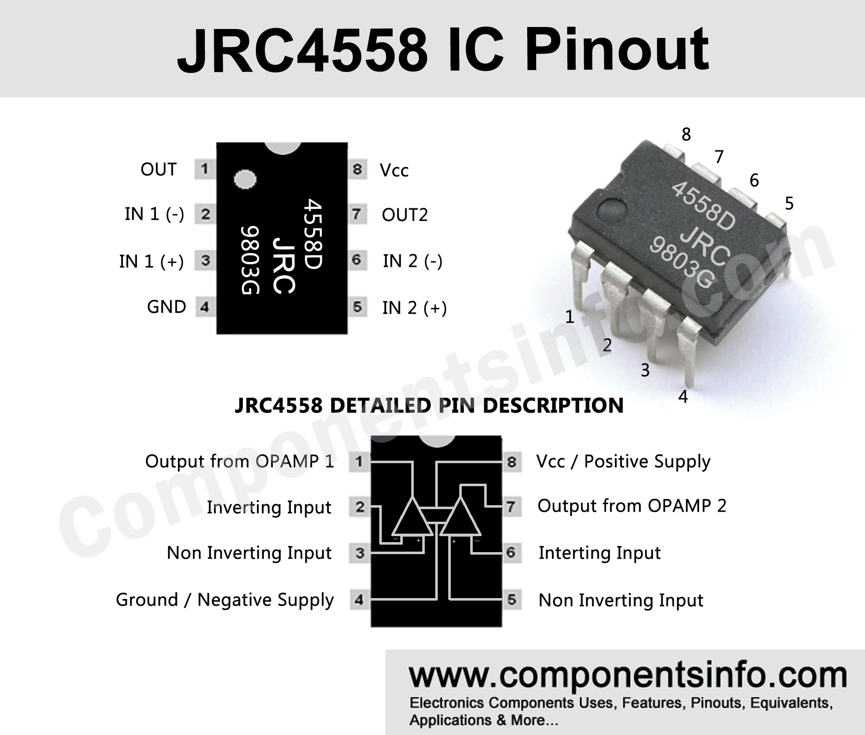
JRC4558 IC Pin Configuration
| Pin# | Pin Name | Pin Description |
|---|---|---|
| 1 | Output A | First Operational Amplifier Output of IC. |
| 2 | Inverting Input A | Inverting Input of IC's First Op-amp |
| 3 | Non Inverting Input A | Non Inverting Input of IC's First Op-amp |
| 4 | Ground (Gnd) | Ground / Negative For Both Op-amps of the IC. |
| 5 | Inverting Input B | Inverting Input of IC's Second Op-amp |
| 6 | Non Inverting Input B | Non Inverting Input of IC's Second Op-amp |
| 7 | Output B | Output of IC's Second Op-amp |
| 8 | Vcc | Positive Supply for both Op-amps of the IC |
JRC4558 Description
JRC4558 is a dual opamp IC available in an 8 pin dip and SOP-8 package. The IC contains two separate op amp inside which can be operated from a single or dual power supply. JRC is a very famous IC among guitar pedal makers and provides very high performance in these types of circuits. Moreover, this IC is also used by electronic students, hobbyists, and tinkerers in their audio projects.
The IC has many features which makes it ideal to use in commercial equipment and devices like low cost and high reliability, high voltage gain, low current consumption, etc. The IC also has a high voltage gain of up to 100dB. The IC has industry standard pin compatibility due to which it can easily be replaced with many substitute dual op amp ICs. The minimum and maximum supply current required by the IC for both operational amplifiers in no load condition is 2.3mA to 4.5mA.
Applications
Comparator Circuits
Guitar pedal circuits
Audio amplifier stages
Audio preamplifiers
Replacement and Equivalent / Other Part Numbers
TLE2072, NE5532, TL072, OPA2134, RC4558, RC4580
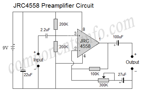
Application Circuit
The figure shows an application circuit of JRC4558 IC, this is a preamplifier circuit built around this IC. As mentioned above JRC4558 is a dual operational amplifiers IC but in this circuit we have used only one internal opamp. This preamplifier circuit can be used for any type of audio pre-amplification you require such as mic preamp, guitar preamp, or other types of audio preamplification requirements. You can also adjust the value a bit higher or lower of the two 200K resistors connected with the pin3 of the IC and adjust the 300K variable resistor to get your desired results. Moreover, you can also play with the capacitor values to get the results you want.
In this diagram, the circuit is operated with a 9V supply which can be a power supply or a battery.
How to Safely Long Run in a Circuit
To get long term good performance with JRC4558 IC it is recommended to always stay under its max ratings. Do not apply more than 15V to the IC, prevent leads from being short-circuited, and always store the IC in temperature above -65 degrees centigrade and below +150 degrees centigrade. The operating temperature should be between -25 degrees centigrade to +85 degrees centigrade.
Datasheet
To download the datasheet just copy and paste the below link in your browser.
https://cdn.datasheetspdf.com/pdf-down/J/R/C/JRC4558-ARTCHIP.pdf