B1560 Transistor Pinout, Features, Equivalent, Applications, How to Use and More
In this post we are going to explore B1560 full part number 2SB1560 transistor. The post contains B1560 transistor pinout, features, equivalent, applications, how to use it in a circuit, safety guidelines and other useful information.
Features / Technical Specifications
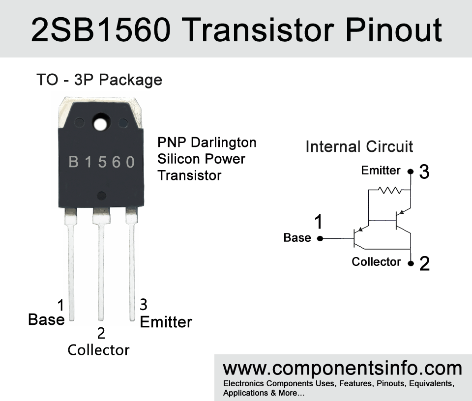
- Package Type: TO-3PN
- Transistor Type: PNP Darlington
- Max Collector Current (IC): -10A
- Max Collector-Emitter Voltage (VCEO): -150V
- Max Collector-Base Voltage (VCBO): -160V
- Max Emitter-Base Voltage (VEBO): -5V
- Collector Power Dissipation (PC): 100W
- Base Current Continuous (IB): -1A
- DC Current Gain (hFE): 5000 to 30000
- Max Storage, Operating & Junction temperature range: -55 to +150 Centigrade
NPN Complementary
NPN Complementary of 2SB1560 is 2SD2390
Replacement and Equivalent
2SB1647
B1560 Transistor Explained / Description
B1560 is a PNP high-gain darlington transistor available in TO-3PN package. The transistor is designed to use in series regulator circuits, audio-related circuits, and general purpose applications. The series regulators are the circuits used to stabilize the output voltage if the input voltage is not stable or it has fluctuations. As mentioned it is also designed to use in audio applications and can be used in variety of audio-related applications due to its high DC current gain which makes it capable amplify the weak audio signal to strong, low saturation voltage which ensures low distortion in signal at its output. Moreover, it is also designed to use in general purpose applications which makes it robust and versatile.
Looking at the absolute max ratings of the transistor the max continuous collector current is -10A, max collector-emitter voltage is -150V, max collector-base voltage is -160V, max emitter-base voltage I s-5V, max continuous base current is -1A and max collector power dissipation is 100W.
The electrical characteristics of the transistor are collector-emitter breakdown voltage (V(BR)CEO) is -150V, the collector-emitter breakdown voltage is the max voltage the transistor is capable to handle which goes through its collector and emitter.
It has maximum collector-emitter saturation voltage (VCE(sat)) is -2.5V on condition IC= -7A; IB= -7mA which shows how much voltage will be dropped across the transistor’s collector-emitter when the transistor is in full conduction mode.
Its base-emitter saturation voltage (VBE(sat)) is -3.0 on condition IC= -7A; IB= -7mA, the base-emitter saturation voltage of a transistor tells us how much voltage this transistor is required to become fully turned ON.
Its DC current Gains (hFE) is from 5000 to 30000, the DC current gain shows the capability of the transistor to amplify the strength of an electrical signal.
It has a collector output capacitance (COB) of 230pF, the (COB) represents the storage of electric charge in a transistor which helps in managing quick changes in voltage and current which occur during the transistor’s switching process and as a result the (COB) makes the transistor’s switching speed high.
The transistor also has very good switching speed, although it is not a very high speed but it is quite acceptable for variety of switching purposes. The turn-on time is 0.8 μs, Storage Time is 3.0 μs and Fall time is 1.2 μs. But if you are designing a circuit that requires a very high speed transistor then you can also check other transistors which are specially designed for high speed applications or purposes.
The transistor is manufactured in three different hFE classifications, each represented by an alphabet written after the part number to determine its gain. If the alphabet is “O”, its hFE will be 5000-2000. If it is “P” the hFE will be 6500-20000 and if it is “Y” the hFE will be 15000-30000.
Where We Can Use it & How to Use
B1560 is a versatile transistor that can be fit in a wide variety of applications. It is not only limited to the applications for which it is designed for and has many other possibilities. It can be used in automotive circuits, charger designs, power-related designs, solar applications, and more.
How to Use:
- To use the transistor in your circuit or design first of all identify its collector, base, and emitter pins.
- Connect a base resistor one pin to the transistor’s base and the other pin to the input signal source. A resistor is an important component to use with the transistor because it limits the current going to the transistor’s base. The transistor is a current controlled device and requires a much less current (in milliamperes) at its base to control the output of the transistor. Without a base resistor a transistor can immediately be damaged.
- Connect the emitter pin with the ground and the load will be connected between the collector and the positive supply rail. The load can be a speaker or any type of component you want to power or control.
- After following the above procedures apply power to the transistor or to the circuit from which the transistor transistor’s pins are connected. The input signal must be provided to the base (through the resistor). Without the input signal, the transistor will remain off.
- At last test the circuit and make adjustments in the base resistor and biasing components to achieve desired results. You can also use a variable resistor between the transistor and the base resistor to check the behavior of the transistor in the circuit by changing the variable resistor value. But a fixed resistor should always be used with the variable resistor or else the transistor could be damaged when the variable resistor value is set to zero.
Applications
Automotive applications
Audio amplifier circuits
Audio preamplifiers circuits
Microphone amplifier circuits
Musical circuits
Voltage stabilizer circuits
Power supply circuits
Battery charger circuits
Battery management circuits
Solar charger circuits
And a variety of other applications.
Safe Operating Guidelines
To get effective and long-life performance it is essential follow the safe operating guidelines to handle the transistor. Below are some of these guidelines to remember when selecting 2SB1560 in your circuit or design.
- Always operate the transistor under its maximum current and voltage limits and stay at least 20% below from all the ratings written in its datasheet under Absolute Maximum Ratings.
- Use a proper heatsink with the transistor to ensure maximum heat dissipation.
- Operate the transistor in its temperature limits written in the datasheet.
- As mentioned above a suitable base resistor is necessary with a base resistor the transistor could be damaged.
- Protect emitter-base junction with reverse polarity you can use a diode if you have a doubt about reverse polarity.
Datasheet
To Download the datasheet just copy and paste the below link in your browser.
https://z3d9b7u8.stackpathcdn.com/pdf-down/2/S/B/2SB1560_SavantIC.pdf