A1275 Transistor Pinout, Equivalent, Applications, Features and Other Important Info
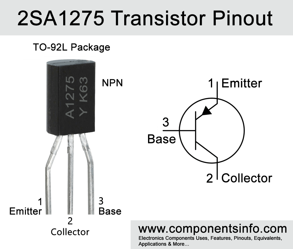
A1275 (full part number 2SA1275) is a PNP transistor available in TO-92L package. This post explains A1275 transistor pinout, equivalent, applications, features and other important info about this transistor.
Features / Technical Specifications
- Package Type: TO-92L Or TO-92MOD
- Transistor Type: PNP
- Max Collector Current(IC): -1A
- Max Collector-Emitter Voltage (VCEO): -160V
- Max Collector-Base Voltage (VCBO): -160V
- Max Emitter-Base Voltage (VEBO): -6V
- Max Collector Power Dissipation (PC): 900mW
- Max Transition Frequency (fT): 50 MHz (TYP)
- Minimum & Maximum DC Current Gain (hFE): 85 – 340
- Max Storage & Operating temperature Should Be: -55 to +150 Centigrade
NPN Complimentary:
The NPN complimentary of 2SA1275 is 2SC3228
Replacement and Equivalent:
2SA1013, KTA1275, 2SB1212
2SA1275 Transistor Explained / Description
A1257 is a silicon PNP transistor available in TO-92L or TO-92MOD package. The transistor is mainly designed for color TV vertical deflection output circuitry and color TV class B sound output.
Color TV Vertical Deflection Output:
In almost all color TV’s there are two circuits which are horizontal and vertical deflection circuits which controls the electrons according to the signals received and create images on the TV screens exactly as the data in the signal received. When you see a complete image on your TV screen it is the result of the scanning of vertical and horizontal electron beam. In horizontal deflection output circuit the electron beam moves from left to right while in vertical deflection circuit the electron beam moves from top to bottom. So what the 2SA1275 transistor does is amplify the signal and controls the vertical electron beam which ensures stable images and also improves image quality and makes them flickering free.
Color TV Class B Sound Output:
Another application of A1275 transistor is color TV class B sound output means this transistor is also used in the output of class B audio amplifier circuits of televisions.
There are many different types of audio amplifiers such as class A, B, AB etc. and each class is different in circuit design and performance. As compared to class A the class B amplifiers are better in performance and are also energy efficient. Moreover, class B amplifier circuits are built using two complementary transistors which ensure better sound quality.
But 2SA1275 is not only limited to the above mentioned applications and due to its versatile electrical characteristics it can also be used in a wide variety of other applications such as in variety of different audio amplification circuits, motors control, switching circuits, etc.
Looking at the maximum ratings of the transistor the maximum collector-emitter voltage is -160V, maximum collector current is -1A, maximum emitter-base voltage is -6V, maximum collector-base voltage is -160V and max collector power dissipation is 900mW.
The transistor comes in three different types according to its DC current gain or hFE which can be determined with the help of the alphabet written on the transistor after its part number. If that alphabet is “R” then its hFE will be 60-120, if “O” then 100-200 and if that alphabet is “Y” then its hFE will be 160-320.
Where We Can Use it & How to Use
As mentioned above A1275 is designed for color TV vertical deflection circuit and class B sound output circuit but apart from that this transistor can also be used for a variety of other purposes such as various types of audio amplification, switching, motor control, LED driving, etc. Using procedure of this transistor is same as we use any BJT transistor.
Applications
Audio Amplifiers
Driver Applications
Switching Applications
Variety of General Purpose Applications
Safe Operating Guidelines
To get good and long term performance it is important to always use the transistor 20% below form its absolute maximum ratings. So the maximum collector current is -1A therefore do not dive load of more than 800mA, the max collector-emitter voltage is -160V so the driven load should be under -128V and the operating and storage temperature should be between -55°C to 150°C.
Datasheet
To Download the datasheet just copy and paste the below link in your browser.
https://z3d9b7u8.stackpathcdn.com/pdf-down/A/1/2/A1275_KEC.pdf


