C1675 Transistor Pinout, Equivalents, Features, Applications and Other Data
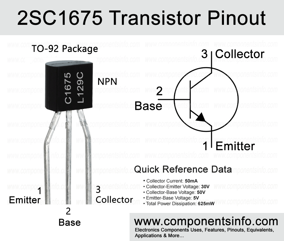
Today we are going to discuss an NPN transistor 2SC1675 available in TO-92 package. It is a low current transistor but it has very good characteristics and features which makes it ideas to use in many electronics applications. This post covers C1675 transistor pinout, equivalents, features, applications and other useful information.
Absolute Maximum Ratings:
- Package Type: TO-92
- Transistor Type: NPN
- Max Collector Current(IC): 50mA
- Max Collector-Emitter Voltage (VCE): 30V
- Max Collector-Base Voltage (VCB): 50V
- Max Emitter-Base Voltage (VEBO): 5V
- Max Collector Dissipation (Pc): 625mW
- Minimum & Maximum DC Current Gain (hFE): 40 – 240
- Max Storage & Operating temperature Should Be: -55 to +150 Centigrade
Replacement & Equivalent
2SC3923, 2SC3245, 2SD779, 2SC1811, NTE382, KTC3400, KTC3205, KTC3203, KTC3200, KTC1026, KTC1006, ECG90, ECG123AP.
2SC1675 Transistor Explained / Description:
2SC1675 which has part number C1675 is an NPN transistor available in TO-92 package. It is a versatile transistor with very good features and characteristics which makes it ideal to use in wide variety of applications.
Looking at the absolute maximum ratings of the transistor, the collector-emitter voltage is 30V, collector current is 50mA, collector-base voltage is 50V, emitter-base voltage is 5V, collector power dissipation is 625mW, junction temperature is 150°C and storage temperature is -55°C to 150°C.
The transistor is available in three different versions according to its DC current gain and these gain values can be identified with the help of alphabetic codes which are R, O and Y. The code “R” indicates the gain of 40 to 80, code “O” indicates the gain of 70 to 140 and code “Y” indicates the gain of 120 to 240.
How to Use This Transistor:
2SC1675 is a bipolar junction transistor. It has three pins: Emitter, Base and Collector. When using the transistor as an amplifier, the emitter pin should be connected to the negative rail of the circuit, the signal that you want to amplify will be applied to the base pin, and the amplified output will be received at the collector pin. However, to build a proper circuit, you will also need to use some passive components, and to use it effectively, you will require some knowledge and experience of electronic circuits.
When using the transistor as a switch, the emitter pin should be connected to the negative rail of the circuit, the signal that you want to use to control the output will be applied to the base pin, and the load will be connected to the collector pin. In switching circuits, you don’t need many passive components to make it work properly. You just need to use a suitable resistor between the signal and the base pin so it provides only the amount of current that needs at the base pin. Only those loads that are voltage sensitive, such as LEDs, etc., require s resistor in their path, otherwise, you can connect your load directly to the collector pin.
Applications:
Audio Amplifiers
Sensor Circuits
Signal Amplification
RF Circuits
Audio Preamplifiers
Darlington Pairs
Switching loads under 50mA
And more…
Safe Operating Guidelines:
For safe operating the transistor, it is important to always use it at least 20% to 30% below its absolute maximum ratings. Always check pinout before placing or replacing the transistor in any circuit, and always stay under this temperature range which are 50°C to 150°C.
Datasheet:
To download the datasheet just copy and paste the below link in your browser.
https://www.alldatasheet.com/datasheet-pdf/view/964466/JIANGSU/2SC1675.html


