BF494 Transistor Pinout, Equivalents, Features, Applications and Other Details
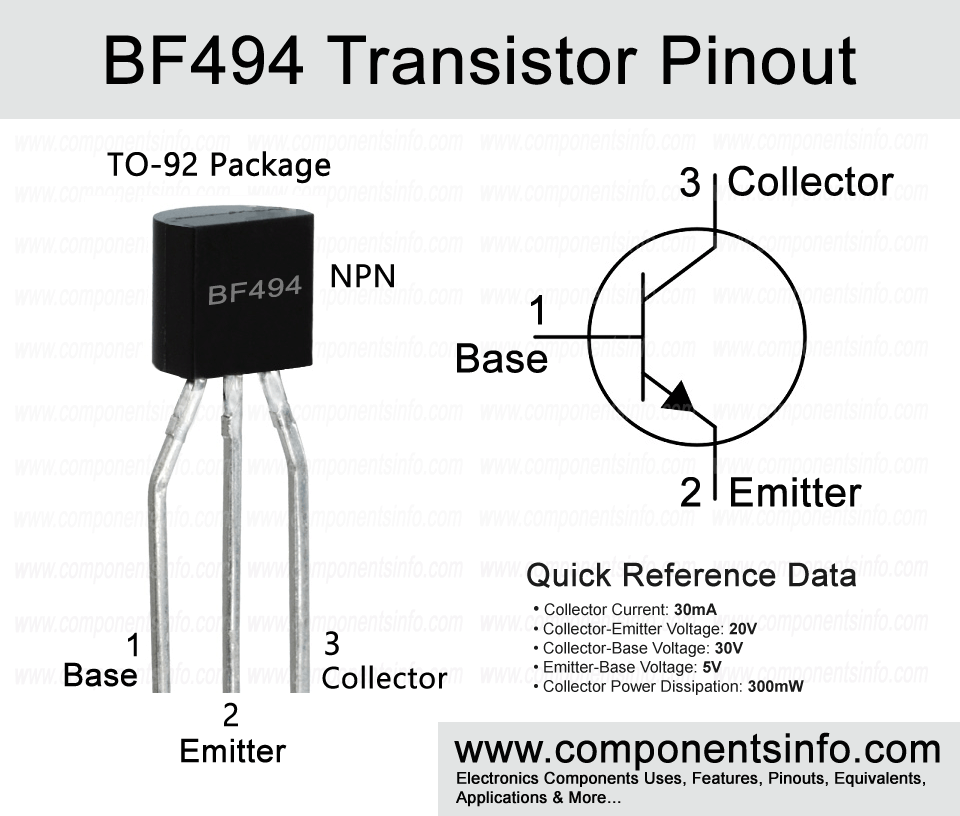
BF494 is an NPN transistor available in the TO-92 package. This post explains the BF494 transistor pinout, equivalents, features, applications and other details about this medium frequency BJT.
Absolute Maximum Ratings:
- Package Type: TO-92
- Transistor Type: NPN
- Max Collector Current(IC): 30mA
- Max Collector-Emitter Voltage (VCE): 20V
- Max Collector-Base Voltage (VCB): 30V
- Max Emitter-Base Voltage (VEBO): 5V
- Max Collector Dissipation (Pc): 300mW
- Minimum & Maximum DC Current Gain (hFE): 40 – 240
- Max Storage & Operating temperature Should Be: -55 to +150 Centigrade
Replacement & Equivalent
BC524, C945, C1815, C9013,2SD756, 2SD955, 2SD2031, 2SD1388, 2SD1146, 2SD1014, 2SC4145 , 2SC2634, BRY56, BF253, BX38, TIPK117, TIPK115, TIPK111.
BF494 Transistor Explained / Description:
BF494 is an NPN transistor available in TO-92 package. It is designed to be used in IF amps, FM tuners, HF applications and oscillators. But it is not limited to these applications only and can also be used in a wide variety of other applications that fall under its absolute maximum ratings.
Looking at the absolute maximum ratings of the transistor, the collector-emitter voltage is 20V, collector current is 30mA, collector-base voltage is 30V, emitter-base voltage is 5V, total power dissipation is 300mW, storage temperature is -65°C to 150°C, junction temperature is 150°C and operating temperature is -65°C to 150°C.
The BF495 that we have discussed previously is almost the same as the BF495, and you can also use it as an equivalent in most cases. But if you can’t find this transistor, then you can also use other equivalent transistors shown above.
How to Use This Transistor:
To use the transistor as a switch, apply a signal (from which you want to control the output load) to its base pin through a suitable current-limiting resistor, connect its emitter pin with the negative rail of the circuit, and drive the load through its collector pin.
To use the transistor as an amplifier, apply the signal (that you want to amplify) to its base through a suitable capacitor, connect its emitter pin with the negative rail of the circuit, and the amplified signal will be available at the collector pin. To make a proper amplifier circuit, you also need to use some passive components, and to use these passive components, you need some knowledge and experience of electronic circuits.
,
Applications:
Audio Amplifiers
RF Circuits
Signal Amplification
Sensor Circuits
Darlington Pairs
Switching loads under 30mA
Audio Preamplifiers
And more…
Safe Operating Guidelines:
For safe operation of this component, do not use it at its absolute maximum ratings and always stay at least 20% to 30% below its absolute maximum ratings. Moreover, always check the pin layout before using it in your circuit and always operate the transistor at a temperature above -65°C and below 150°C.
Datasheet:
To download the datasheet just copy and paste the below link in your browser.
https://www.alldatasheet.com/datasheet-pdf/view/16211/PHILIPS/BF494.html


