4N25 Optocoupler Pinout, Datasheet, Equivalent, Features and Other Information
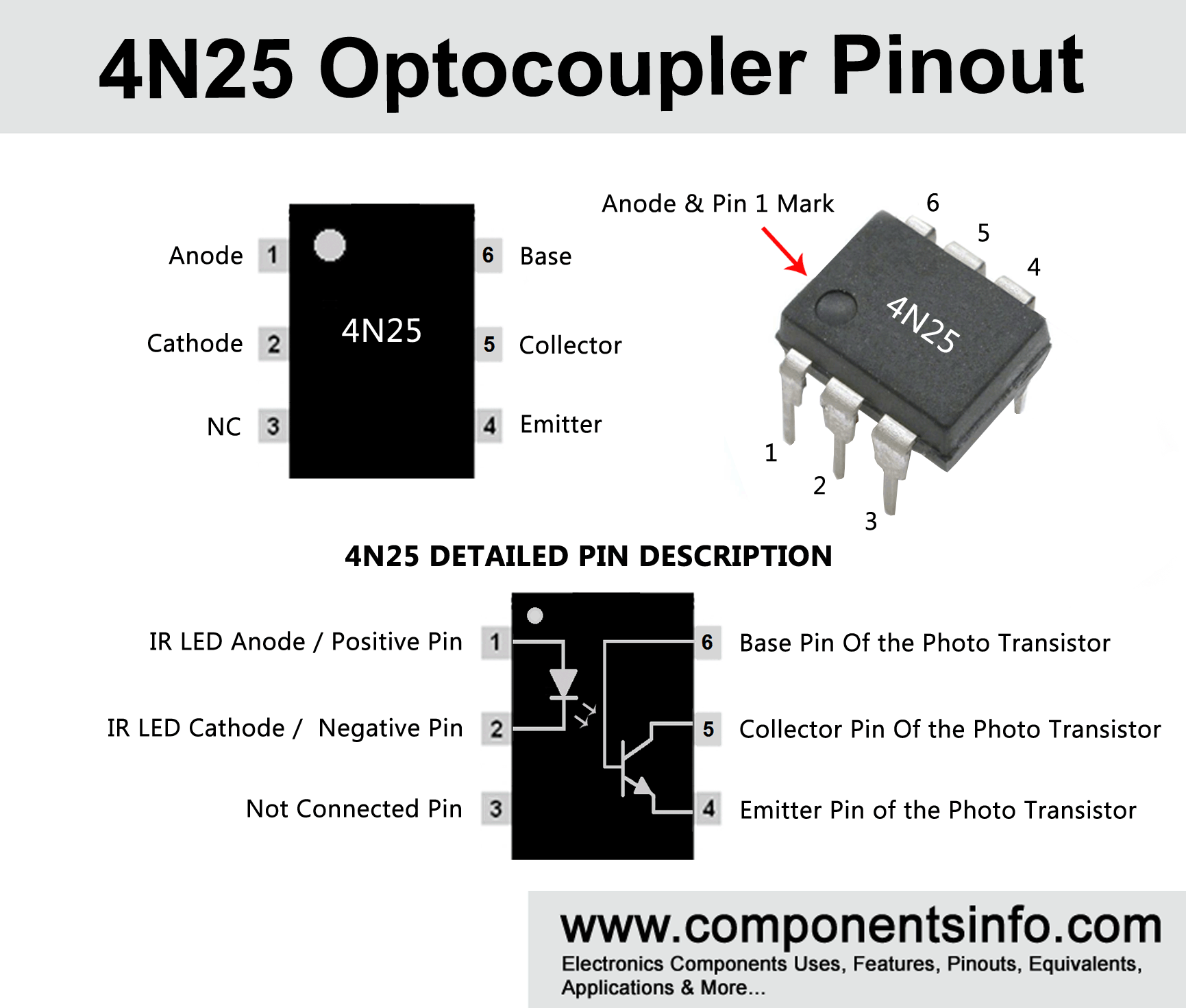
4N25 is a general purpose optocoupler , this article covers 4N25 optocoupler pinout, datasheet, equivalent, features and other information on how to use and where to use this device.
4N25 Features / Technical Specifications
- Package Type: 6 Pin Dip & SMD
- Transistor Type: NPN Photo Transistor
- Photo Transistor Max Collector Current(IC): 150mA
- Photo Transistor Max Collector-Emitter Voltage (VCEO): 30V
- Photo Transistor Collector-Emitter Saturation Voltage : 0.15 to 0.5
- Photo Transistor Max Emitter-Collector Voltage (VECO): 7V
- Photo Transistor Max Collector Dissipation (Pc): 150 Milliwatt
- LED Max Reverse Voltage (VR): 3V
- LED Max Forward Current: 60 Milliampere
- LED Max Power Dissipation: 120 Milliwatt
- Max Operating & Storage Temperature Should Be: -55 to +100 Centigrade for Operating & -55 to +150 for Storage.
4N25 Optocoupler Explained / Description
4N25 is also a widely used optocoupler / optoisolator / photocoupler, It is a general purpose optocoupler like PC817, MOC3021 etc. It is manufactured in 6 pin dip package and SMD package. The device consists of one IR LED and one phototransistor / Detector which detects the light comes from the IR LED. 4N25 also having the base pin of the detector transistor connected with the pin6 of the body hence the user can control transistor by two inputs one from the IR LED light which is connected to pin1 and pin2 and other from controlling the transistor with its base.
The phototransistor can handle max 30V and max150mA across it collector-emitter. Moreover the collector-emitter saturation voltage is from 0.15 to 0.5 which is ideal to use in applications where voltage saturation is required. The max forward current of the IR LED is 60 milliampere and the max power dissipation of the IR LED is 120 milliwatt. The pin3 is a NC pin that is also shown in the 4N25 pinout or pin diagram above “NC” means it is not connected with the internal circuitry of the device.
Applications
Isolation between two circuits
Output of Microcontrollers
Power supplies and chargers
Digital circuits
Telecommunication Circuits
AC Detector
AC Isolation
Replacement and Equivalent Part Numbers
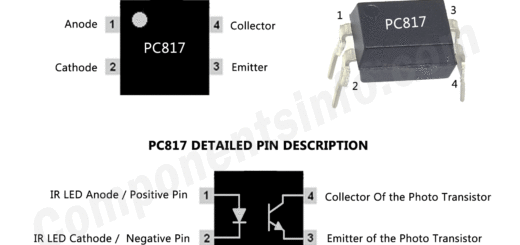
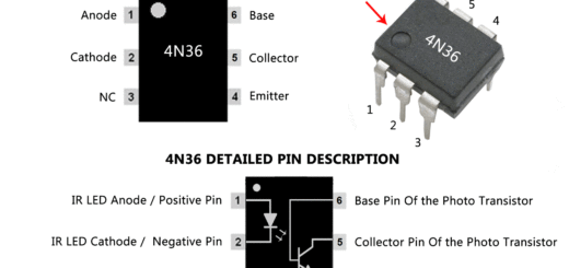
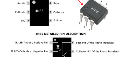
4N25 replacement and equivalent optocouplers are 4N26, 4N28, PC817, PC816, 4N27, 4N35, 4N36 & H11Ax series.
Where TO Use 4N25 Optocoupler
4N25 optocoupler can be used for variety of purposes and requirements in electronic circuits. For example it can be used in electronic applications where there is a chance of voltage surge or spikes which most of the time damage the electronic circuits and components due to which it can be used for the safety of the components. The photocoupler isolates one circuit from the other so you can use it easily when there is a requirement of isolation between two circuits. Apart from this it can also be used as voltage detector in AC and DC operated circuits, output of microcontroller to operate other devices and applications from microcontrollers, controlling relay, controlling mosfet and other high power transistors, high voltage circuits, controlling AC and DC high voltages etc.
How TO Use 4N25 Optocoupler
Using 4N25 optocoupler is pretty straight forward; this optoisolator contains 6 pins as shown in the above 4N25 pinout diagram. The LED side of this or any other optoisolator is connected just like any other normal LED like Anode pin with the positive and cathode pin with the negative or ground. Now connected the Anode pin (Pin1) with the output you want to use the output should be positive and the cathode pin (Pin2) be should be connected with negative or ground of the same circuit. Now the other part of the device which is the phototransistor, the phototransistor have two base one is connected with the photo detector which detects the IR LED light and switches ON the transistor and the second one is connected with pin 6 which also switches ON the transistor when current is applied on the base. Hence the phototransistor can be operated like a general BJT transistor and also like a phototransistor or the user can also use the transistor in both ways for example one signal output is connected with the IR LED and the other signal output is connected with the base of the transistor.
How to Safely Long Run in a Circuit
To get long term performance with this device it is suggested that the user should always stay below the absolute max ratings. The maximum load the device can handle is 150mA therefore do not connect load more than 150mA. Always use a suitable current limiting resistor with the IR LED. Always operate in temperature above -55 centigrade and below +100 centigrade and store in temperature above -55 centigrade and below +150 centigrade.
4N25 Datasheet :
To Download the datasheet just copy and paste the below link in your browser.
https://pdf1.alldatasheet.com/datasheet-pdf/view/50072/FAIRCHILD/4N25.html


